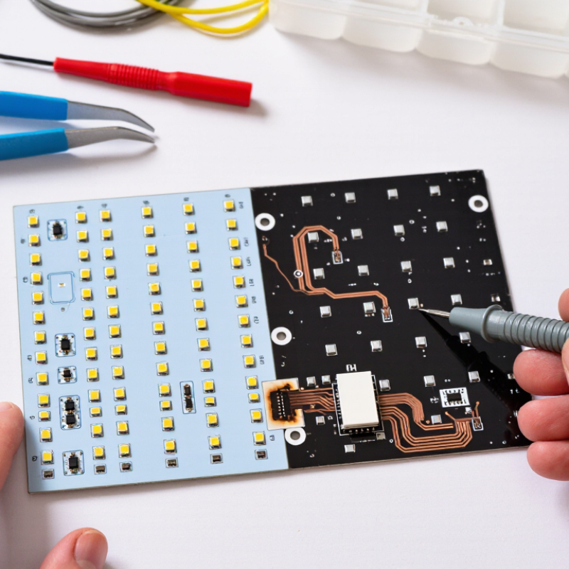
| Definition of a dead section |
A localized part of the LED sheet remains dark while other areas still illuminate. |
An open circuit, failed LED group, damaged conductive trace, or loose connection. |
Visually compare the dark area with a working area and inspect the electrical path. |
Trace the fault from the power input toward the first unlit section before replacing parts. |
Easy |
| Entire sheet is dark |
No LED area lights up. |
No input power, failed power supply, blown fuse, incorrect polarity, or disconnected connector. |
Measure the supply output with a multimeter and verify polarity against the sheet specifications. |
Restore the correct low-voltage supply, replace a suitable fuse, or reseat the connector. Do not bypass protection devices. |
Moderate |
| One section is dark from the start |
A clean boundary separates the illuminated and unlit areas. |
An open trace, broken solder joint, damaged jumper, or failed series LED group. |
With power disconnected, perform continuity checks across connectors, jumpers, and visible traces. |
Repair a minor connector or solder-joint fault; replace the affected modular section if the LED group itself has failed. |
Moderate |
| Section flickers before going dark |
The area flashes, dims, or responds when the sheet or cable is moved. |
Loose terminal, cracked solder joint, damaged cable, or intermittent trace. |
Inspect while unpowered, then perform a controlled voltage and continuity check by a qualified person. |
Secure the connection, repair the joint, or replace the damaged cable. Avoid bending the sheet at the fault location. |
Moderate |
| Dim or discolored section |
The section is not fully dark but is noticeably dimmer, warmer, or a different color. |
Voltage drop, overloaded wiring, poor heat dissipation, aging LEDs, or a partially damaged circuit. |
Measure voltage at the input and far end of the affected section; inspect for heat marks. |
Correct cable sizing and connections, improve thermal conditions, or replace the degraded section. |
Moderate |
| Repeated failure after replacement |
A repaired or replaced area fails again within a short period. |
Incorrect voltage, excessive current, heat buildup, moisture, mechanical stress, or poor installation. |
Check the power supply rating, operating temperature, mounting surface, ventilation, and moisture exposure. |
Remove the underlying cause before installing another section; use only electrically compatible replacement parts. |
Advanced |
| Visible physical damage |
Cuts, creases, lifted pads, burnt areas, corrosion, or delamination are visible. |
Improper handling, impact, sharp bending, liquid ingress, or excessive heat. |
Disconnect power and inspect under good lighting; do not energize a wet or burnt sheet. |
Replace the damaged module or sheet section. Small trace repairs are suitable only when the substrate remains safe and intact. |
Advanced |
| Incorrect replacement part |
The new section is dark, uneven, overheats, or causes the power supply to shut down. |
Mismatched operating voltage, current, polarity, connector, dimensions, or control method. |
Compare electrical ratings, polarity, connector pinout, dimensions, and control requirements. |
Use a replacement with matching electrical and physical specifications; never rely on appearance alone. |
Moderate |
| Power and safety check |
The repair requires access to wiring, terminals, or a power converter. |
Electric shock, short circuit, overheating, or fire risk if the circuit is handled incorrectly. |
Switch off and isolate power; verify absence of voltage before touching conductors. |
Use insulated tools and suitable protection. Have a qualified electrician handle mains-voltage sections. |
Critical |
 Zionsville Lighting